The solution to this problem, like most problems, is simple as long as you know the answer.
Ubiquiti WiFi access points such as this UAP AC Lite are designed to be affixed to ceilings.
The actual access point is attached to a base that is firstly affixed to the ceiling.
The access point is then fitted to the base and rotated so that the tang on the base (arrowed) goes over the rotational stop and locks in to the slot of the access point.
To remove the access point the tang of the base needs to be raised so the access point can be rotated and removed. This is easy when the unit is not fitted to the ceiling as you can lift it with your finger.
When it is fitted to the ceiling though you have to insert an object through the small access hole (arrowed) and lift the tang
No keys or tools are supplied with the access point for removal. Screwdrivers don't really fit into the access hole as they are too big and there is not much room available when the access point is fitted to the ceiling.
The ideal solution is a steel wire paper clip. The bigger the better as long as the wire diameter of the paper clip goes through the access point hole, This 50mm long paper clip seems the ideal size.
With a pair of needle nose pliers, straighten out the outside bend as shown.
Then bend the now straight portion back around to 90°
Now half way between the 90° bend and the end of the wire, bend the wire 45° to the left and then 5mm closer to the end of the wire put another 45° bend in this time to the right.
The bent paper clip can now be inserted into the access hole of the access point.
Now rotate the paper clip up the the left, the 45° bends in the wire lift the tang clear of the rotational stop.
The access point can now be rotated anti clockwise (looking from underneath) and removed from the base unit.
A simple solution to a tricky problem that can be made with an item found in any office or home.
Malcys Adventures in Computer Land
A blog to help me remember how to fix problems on various computers. If anyone else reads this blog and finds it useful that will be a bonus
Saturday, 10 September 2016
Sunday, 4 September 2016
Installing PFSense on Soekris NET6501 with mSATA drive
A Soekris NET6501 is a small single board PC that can be used in a variety of roles. In this case it is being used for running PFSense an open source firewall program. There are several different NET6501 boards that vary on CPU speed memory and Ethernet ports. This board is a NET6501-50 in a 19" rack mount case but the instructions should work on other variants.
First step was to install the mSATA drive onto the 6501. The various ports on the board seem to be sharing buses so you may have to experiment if you are using USB and other ports but this location for the mSATA worked fine for me
First step was to install the mSATA drive onto the 6501. The various ports on the board seem to be sharing buses so you may have to experiment if you are using USB and other ports but this location for the mSATA worked fine for me
Next we need to download PFSense to load on to the 6501, this is where it starts getting tricky.
PFSense is built on Free BSD. Since PFSense version 2.2 it has been built using version 10.x of Free BSD. There seems to be an issue with Free BSD version 10.x that stops the 6501 board from booting from the mSATA drive after PF Sense has been installed. The latest version of PFSense is 2.3.2 and still has the problem of booting from mSATA.
I got around this issue by loading an older version of PFSense and then upgrading from within that version of PFSense.
The version of PFSense I used was 2.1.3 this does not appear as an option to download from the main PFSense site so you may have to dig around on the internet to find it. I found it at this mirror site.
The version that I used was
This is used it install via a USB memory stick and has a serial console
Download the file and write it to a memory stick and make sure that the memory stick is bootable, I used a Windows program called Rufus or use your other favourite memory stick writing program.
Once you have PFSense 2.1.3 on a memory stick and you have your mSATA installed in your 6501 you are nearly ready to install
If you are connecting to the 6501 via the serial port you will need a program such as Putty. Putty initially needs to be set to 19200 8 data bits 1 stop bit and no parity to talk to the 6501 but you will also need 9600 and 115200. This is because PFSense 2.1.3 uses 9600 but when you update to the latest version that will use 115200.
When you boot the 6501 you should see a screen as below when it has booted
Type Show
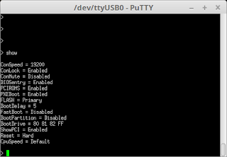
You can see the console speed is set to 19200 and the bootdrive is set to 80 81 82 the mSATA drive will be 80 and the USB memory stick will be 81. You can change these settings if you want to but you will have to take the console lock off first by typing
ConLock=disabled
If you are happy with the settings insert the memory stick into the USB port next to the console port and make a short press on the reset button
The 6501 will reboot and seem to have rubbish on the screen
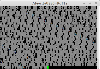
Restart Putty at 9600 and connect to the 6501 you should then see that PFSense is loading from the memory stick
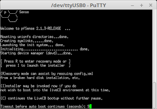
Pressing I will invoke the installer.
Install PFSense by following the on screen menus
You should have the 6501 connected to your network via an Ethernet cable
The Quick and Easy option worked for me
When the progress bar reaches 100% you should see this screen
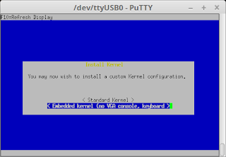
Select "Embedded Kernel" this will allow the serial port to still work after reboot the standard kernel will not. Some more data will be written to the mSATA before you see this screen
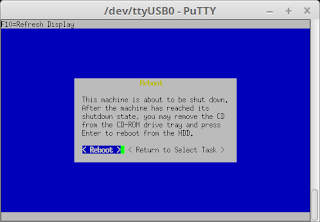
Select "Reboot" Hopefully the 6501 will reboot into the installed PFSense on the mSATA and not the memstick installer program. If it does boot the installer remove the memory stick and reboot the 6501. If it still does not boot check the bootdrive setting of the 6501 it should be 80 first.
Hopefully PFSense will run correctly and you should see this screen, Select "n" for setting up the VLANs
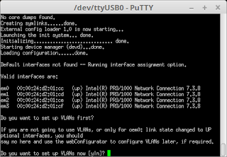
Select "a" for auto detection of the WAN interface
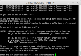
Connect the network to the 6501 ETH 0 port, if already connected remove and reinsert the cable. Then press "ENTER"
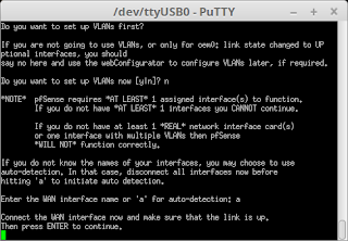
The connection should have been detected, if not repeat auto detection and and remove and reinsert the cable until it is.
You will then be asked about setting up the LAN interface, we can ignore that at this point, Just hit enter
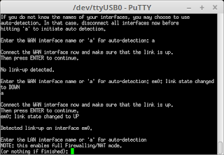
select "y" to assign the WAN interface

Eventually you should see this screen
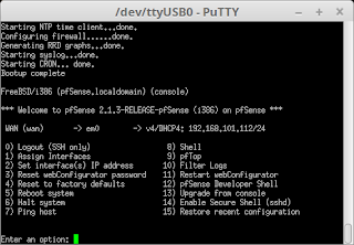
Option 13 should allow you to update PFSense from the console but I had no luck doing it that way. However I did do it this way.
Using you favourite browser connect to the ip address shown for the WAN, in this case 192.168.101.112

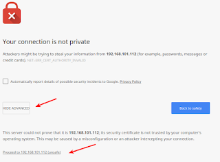
You will probably get a message saying your connection is not private, click advanced and then proceed
Login to PFSense. The user name is admin and the password is pfsense

Click the logo at the top of the screen to stop the wizard

On the Dashboard click on "Click Here" next to Update Available
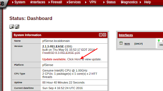
Click the "Invoke Auto Upgrade" button
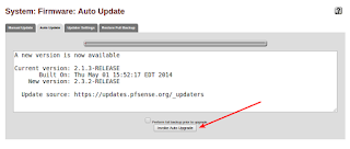
The new version will down load, install and reboot the 6501
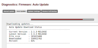
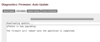
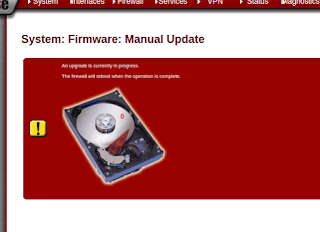
PFSense will eventually reboot, it may take 5 mins or more. If you now want to contect to PFSEnse with the serial console then you will have to use Putty set at 115200.
As you can see PFSense is now at version 2.3.2

Logging back in with you browser also shows PFSense at the latest build
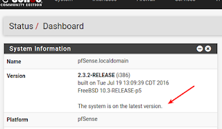
You now need to set up PFSense to your requirements.

You can see the console speed is set to 19200 and the bootdrive is set to 80 81 82 the mSATA drive will be 80 and the USB memory stick will be 81. You can change these settings if you want to but you will have to take the console lock off first by typing
ConLock=disabled
If you are happy with the settings insert the memory stick into the USB port next to the console port and make a short press on the reset button
The 6501 will reboot and seem to have rubbish on the screen

Restart Putty at 9600 and connect to the 6501 you should then see that PFSense is loading from the memory stick

Pressing I will invoke the installer.
Install PFSense by following the on screen menus
You should have the 6501 connected to your network via an Ethernet cable
The Quick and Easy option worked for me
When the progress bar reaches 100% you should see this screen

Select "Embedded Kernel" this will allow the serial port to still work after reboot the standard kernel will not. Some more data will be written to the mSATA before you see this screen

Select "Reboot" Hopefully the 6501 will reboot into the installed PFSense on the mSATA and not the memstick installer program. If it does boot the installer remove the memory stick and reboot the 6501. If it still does not boot check the bootdrive setting of the 6501 it should be 80 first.
Hopefully PFSense will run correctly and you should see this screen, Select "n" for setting up the VLANs

Select "a" for auto detection of the WAN interface

Connect the network to the 6501 ETH 0 port, if already connected remove and reinsert the cable. Then press "ENTER"

The connection should have been detected, if not repeat auto detection and and remove and reinsert the cable until it is.
You will then be asked about setting up the LAN interface, we can ignore that at this point, Just hit enter

select "y" to assign the WAN interface

Eventually you should see this screen

Option 13 should allow you to update PFSense from the console but I had no luck doing it that way. However I did do it this way.
Using you favourite browser connect to the ip address shown for the WAN, in this case 192.168.101.112
You will probably get a message saying your connection is not private, click advanced and then proceed

Login to PFSense. The user name is admin and the password is pfsense

Click the logo at the top of the screen to stop the wizard

On the Dashboard click on "Click Here" next to Update Available

Click the "Invoke Auto Upgrade" button

The new version will down load, install and reboot the 6501


PFSense will eventually reboot, it may take 5 mins or more. If you now want to contect to PFSEnse with the serial console then you will have to use Putty set at 115200.
As you can see PFSense is now at version 2.3.2

Logging back in with you browser also shows PFSense at the latest build

You now need to set up PFSense to your requirements.
Sunday, 9 November 2014
"Backups, why do I need to do backups?"
One thing that I find in common when I speak to people about problems that they are having with either their desktop or laptop, is that most people dismiss backups as an irritant that they can do without. They have never lost any data in the past so what will change in the future?
Having had some success in persuading people that they do need to do backups in one form or another (usually a failed or very poorly hard drive focuses the mind) I still find that it is an uphill struggle. University students are usually the best recipient to my mantra of "there are only three things to remember 1. Do your backups 2. Do your backups and 3. Do your backups. I usually also tell them the story of the third year medical student with a very poorly hard drive in their laptop and no backups, nothing - zero - zilch - nada. If it wouldn't come off that failing hard drive it was gone forever. Focus the mind, do you really want to lose all that work?
So why all the ramblings about backups?
Well I received a call from home this week asking why there was a funny smell in the garage? No idea was my reply. Then our son rings home and asks if the internet was off as he could not pick up his email. Aha light bulb moment. Son gets wife to check email server for power lights, there were none. "Pull the power lead out the back Mum, NOW!"
So what did I find when I got home? The email server is running on a HP ML110 G5 server with two 250GB SATA hard drives in Raid 10. One of the hard drives failed around 12 months away and was replaced and the raid rebuilt from the remaining good hard drive. When the side of the server was removed it was quite clear what had happened.
The lower of the two hard drives had suffered a melt down of the power connector.
When moving the power connector the power leads fell out of what was left of the melted connector. There was no insulation left on the cables and the copper conductors had fused together.
This is what was left of the power connector, just a big blob of plastic. You will see that I had plastic gloves on, mainly because of the soot but also because I was not sure if the melted plastic would be dangerous, some plastics can be toxic when burnt.
This was the upper hard drive. The power connector and the sata cable had melted but luckily the hard drive only suffered from superficial smoke damage. I did wonder if the hard drive had been heated to such a point that the solder would have melted.
I think that there were actual flames inside the server due to the amount of smoke and soot evidence.
A close up of the memory modules shows the amount of soot that had been deposited.
The soot being mainly carbon and therefore conductive, I thought it was wise to clean off as much as possible. With the careful use of some isopropyl wipes I was able to clean up the upper hard drive and the memory modules. Luckily the hard drives were as far apart as possible, if they had been on top of each other I don't think the upper one would have survived, I also changed the PSU out for another one that I had and also vacuumed out all the burnt bits of plastic, finally I then blew out any remaining remnants with compressed air.
The power was reapplied and low and behold it all came back to life. No lost data due to the second dive of the raid array still working, if that had failed we did have an external backup as well but that would have resulted in some data loss due to the gap in time since the last backup.
So the morel is make sure you do your backups and make sure they are external to the device.
Monday, 30 December 2013
Ubuntu resolution problem
(or never overlook the obvious)
The problem
Over the years I have mainly used Windows based PCs but have also dabbled with Linux based systems. I have tried a few different Linux distributions but have settled on Ubuntu as my distribution of choice.
There was one problem that I was never able to resolve, that was really bugging me. When I connected my Linux box to a monitor via the VGA connector I could never set a usable resolution. My pair of Dell 22" run at a native 1920 x 1080 but I was lucky if I could get it working at 1024 x 768 which is also a 4:3 aspect ratio rather than the native resolutions 16:9 making squares look like rectangles and circles look squashed.
If I connected the PC via a digital connection such as a DVI or HDMI cable the resolution was always correctly selected. The left hand green monitor is connected with a DVI cable and the right hand yellow monitor is connected by a VGA cable. This was going to be a problem as I was planning on setting up a Linux Ubuntu PC as a replacement for an ageing Windows XP PC for a friend that is the wrong side of 70, who only had a VGA monitor.
The non solution
The graphics card in the PC that I had Ubuntu loaded on to it had Nvidia chipset loaded on to it. Researching the problem on the internet it seemed that the Nvidia drivers could be an issue, so I tried many different variations of driver from the Nvidia stable as well as the Ubuntu Nouveau drivers. There were also articles stating that you could insert custom resolutions into an xorg file. On several occasions I broke my Linux installation to such an extent I had to reinstall it.
Now I am not too bad when it comes to PC use (usually Windows), but the problem I have found with Linux in general, is that if you want to do anything more than basic things you need to have a reasonable knowledge of the Linux operating system, but you can't get that reasonable knowledge because you can't do anything but the basics. A bit of a Catch 22 situation. So playing around with xorg and drivers can seem a bit daunting and very frustrating.
In Windows you have the option of choosing the resolution and refresh rate that you want to run the monitor at. It is up to you to apply the correct settings. With Ubuntu, and probably other Linux distributions, the operating system tries to determine the correct resolution so as not to apply a resolution that could potentially damage the monitor.
After many attempts at getting a usable resolution on VGA I was frustrated and resigned my self to just being able to connect via DVI.
The real solution
My pivotal moment was when I realised that my Sons dual monitor Ubuntu setup was using DVI and VGA connections just like mine, but he was using the correct resolutions on both monitors. In my defence he is away at university most of the year and I thought both monitors were connected via DVI.
With this small piece of information I started investigating my resolution problem with renewed vigour knowing that it was possible to run a VGA monitor in Ubuntu at the correct resolution.
So where does the problem lie? Well what you have to understand first is my PC setup. I don't just have an Ubuntu PC, I have two PCs at my desk. My main PC (at the moment) is a Windows 8 machine that sits in the cupboard to my left, and an Ubuntu box at my feet. I have twin 22" Dell monitors that each have a DVI and VGA input. The Windows box runs on a single graphics card that has a a VGA and DVI output. Therefore one monitor is connected to the Windows box via VGA and the other via DVI. This means that there is a spare input into each monitor, these are therefore available for the Ubuntu box at my feet. When I want to use the Ubuntu box I just switch the input on the monitor. Before fixing the problem I connected the Ubuntu box to a monitor using just the DVI cable and therefore using just one monitor rather than the twin monitor set-up that the Windows PC has.
The monitor on the right is the one that is connected to the Ubuntu box via VGA and was the one that I could never set to the correct resolution. To try and keep the cables relatively tidy they are cable tied and routed in a way that means that I don't catch them with my feet. This meant that the VGA cable that was supplied with the monitor would not reach the Ubuntu box at my feet.
A cable that is not long enough is not a problem as there are many solutions, I could have bought a longer cable or I could use an extension cable. Well I had a good quality VGA extension cable made by Belkin which is what I had used for quite a while and had served me well when I was working on Windows PCs.
It had a nice thick cable, was a reasonable length, it even had gold plated connectors what more could I want?
Well it seems that I need just a little bit more. A good resource on VGA pin outs is the Wikipedia VGA page It would seem that my high quality Belkin VGA extension cable does not have all of the pins connected. Pin 9 is missing completely from one end but this seems to be a +5v power feed and does not have any affect in my set up. More importantly pins 12 and 15 are not connected through. Pins 12 and 15 appear to be involved with an I2C bus between the monitor and graphics card that is used to identify the monitor to the graphics card so that the monitor know what the monitors supported resolutions are. Eureka!
To prove the theory I plugged the monitor VGA port directly in to the graphics card without the extension lead. Success I could now choose the correct resolution for the monitor
So now I had to locate a VGA extension cable that had all of the pins connected. This was not as difficult as I thought it would be, however you have to be careful, you can't go by price, brand, size of cable or whether any part of it is made of gold. It needs to explicitly state that all pins are connected in the description. In the end I opted for a very expensive (not) lead from an Amazon seller for about £3.
The cable is thinner than the Belkin, shorter than the Belkin, has less gold than the Belkin but it enables me to run my VGA monitor at its correct resolution. Result!
So the lesson learnt here is to never overlook the obvious. This cable worked perfectly under Windows where I was able to select the correct resolution, but not under Ubuntu which was trying to query the monitor over the non-existent I2C bus.
So I have a twin monitor Ubuntu set-up but more importantly my 70+ year old family friend now has a fresh PC running Ubuntu, instead of her old XP set-up.
Sunday, 4 August 2013
Help! I've got a hard drive.
So you have an old hard drive. There are several reasons why you may have a old hard drive
If you have bought a new PC then you may want to either use the old PC as a secondary PC at home, maybe one for the kids or donate it to a charity for reuse or donate it to a relative. Information on either securely wiping the drive or just wiping your data can be found HERE, Re using the old equipment as much as you can is the best thing to do, it can save precious resources and stop waste going to landfill or being exported to third world countries.
However sometimes the best thing to do is to get rid of the old equipment, it's either faulty or so old that it is no use to anybody.
I have had people ask my what to do with their old PC tower before taking it to the recycling point. They think that if they smash it with a hammer they will render it useless. They might but they could also leave the hard drive untouched meaning that the data could potentially be recovered from the hard drive easily.
My preferred method is to take the hard drive to pieces. Hard drives contain items that can be useful for the tinkerer. The hard drive disk itself make excellent mirrors that are virtually unbreakable, ideal when working on cars etc. There are a pair of super strong magnets in the hard drive that can be used for magnetic type things, watch out though they can pinch! If you are feeling really geeky you can take out the platter drive motor and have a play with it Like this.
The tools that you will need to take your hard drive apart are few, screwdrivers, Torq drivers and a pair of pliers or cutters to persuade some of the Torq screws that can be a little tight.
The parts from the stripped down hard drive that you don't think will be useful can be recycled. The main body is usually aluminium and the top is steel, you can use the magnet to test. My local recycling center has separate bins for steel, aluminium and electronics so I feel I am doing my bit to help the recycling effort.
You also get a better insight into how your hard drive worked, I can pretty much guarantee that it won't work again after this and that sort of makes your data pretty much irretrievable. If you are still worried you can wipe the drive before taking it to bits.
The time lapse video below shows me taking apart an 80GB 3.5" IDE Seagate drive. 3.5" drives have the biggest magnets. Most 3.5" drive are similar in there construction so come apart in a similar way.
- You may have bought a new PC and you are wondering how to safely dispose of the old PC
- Your old hard drive may be faulty and you have changed it for a new one
- You may have upgraded the old hard drive for a newer bigger one
If you have bought a new PC then you may want to either use the old PC as a secondary PC at home, maybe one for the kids or donate it to a charity for reuse or donate it to a relative. Information on either securely wiping the drive or just wiping your data can be found HERE, Re using the old equipment as much as you can is the best thing to do, it can save precious resources and stop waste going to landfill or being exported to third world countries.
However sometimes the best thing to do is to get rid of the old equipment, it's either faulty or so old that it is no use to anybody.
I have had people ask my what to do with their old PC tower before taking it to the recycling point. They think that if they smash it with a hammer they will render it useless. They might but they could also leave the hard drive untouched meaning that the data could potentially be recovered from the hard drive easily.
My preferred method is to take the hard drive to pieces. Hard drives contain items that can be useful for the tinkerer. The hard drive disk itself make excellent mirrors that are virtually unbreakable, ideal when working on cars etc. There are a pair of super strong magnets in the hard drive that can be used for magnetic type things, watch out though they can pinch! If you are feeling really geeky you can take out the platter drive motor and have a play with it Like this.
The tools that you will need to take your hard drive apart are few, screwdrivers, Torq drivers and a pair of pliers or cutters to persuade some of the Torq screws that can be a little tight.
The parts from the stripped down hard drive that you don't think will be useful can be recycled. The main body is usually aluminium and the top is steel, you can use the magnet to test. My local recycling center has separate bins for steel, aluminium and electronics so I feel I am doing my bit to help the recycling effort.
You also get a better insight into how your hard drive worked, I can pretty much guarantee that it won't work again after this and that sort of makes your data pretty much irretrievable. If you are still worried you can wipe the drive before taking it to bits.
The time lapse video below shows me taking apart an 80GB 3.5" IDE Seagate drive. 3.5" drives have the biggest magnets. Most 3.5" drive are similar in there construction so come apart in a similar way.
Monday, 11 March 2013
HP 2600n Colour Laser Printer
Magenta fade and poor printing
I have a HP 2600n colour laser printer, which I have had for
around 5 years and it has proven to be a very reliable printer. However
recently we noticed that the colour printing quality was not as good as it used
to be. To start investigating I printed a demo page (press left and right arrow
together).
The demo page showed that there were slight problems with
the alignment of the four different coloured toners. It also shows, but is not
as easy to spot, a problem with the magenta toner. You think that the magenta
is OK as the soldier’s tunic is red so you assume that the magenta is working
fine.
To further prove that there was a problem I went to this
page from Refresh Cartridges and printed out the test page for colour
laser printers. What that showed was that the magenta was fading on the left of
the page.
Doing a quick search I found that this is a very common
fault with this printer and the other printers that are based on the same
workings such as the HP 2605 and HP 1600 and the Canon LBP5000. The problem is
due to dust on one of the mirrors that the laser beam is reflected off on its
way to the toner cartridge.
The optical box that contains the lasers, lenses and mirrors
is not sealed against ingress of dust, and as the printer has fans to cool the
internal workings of the printer, the result is that the fans suck dust in from
outside the printer and deposit it inside the printer. If I was a cynical
person I might think that the printer was specifically designed that way to try
and get people to buy a new printer, after buying a new magenta cartridge that didn't fix the fading problem!
The optical box looks complicated, and it is, but it’s not
as complicated as it seems on first glance. There is basically one set of
mirrors and lenses that have been copied another three times to give a set of
lasers, lenses and mirrors for each of the four different colours.
Each one of the four different coloured sections is made up
of the following basic components:
- Laser – covered by shutter in picture
- Lens
- Rotating mirror – only one per pair of colours
- Lens
- Mirror – this is where most of the dust will be
- Compensating lens
- Calibration detector – only one per pair of detectors
The laser beam is emitted from the laser through the lens which focuses the beam on to the rotating mirror which then reflects the
beam through the next lens and onto the mirror. The beam is the reflected
through the compensating lens and onward to the toner cartridge. If you
look carefully at the lens before the rotating mirror, you will see that there
are actually three lenses moulded in to the plastic. Two of them are the lens
that the two laser beams pass through before hitting the rotating mirror. The
third one focuses the beam on to the calibration detector which is located back
on the pcb.
All the lenses are made of plastic and care must be taken in
cleaning them as they are easily scratched. The mirrors are also delicate as
the reflective surface is on top of the glass and not behind the glass in a
normal mirror. The magenta and yellow mirrors are particularly susceptible because
the face upwards and any dust floating down will settle on them.
I came across an
excellent site that takes you through the fix step by step. I am not going to
repeat the steps but just going to point you towards the excellent site.
I recommend that you follow the instructions on the above
site and then read the extra problems that I overcame.
The
good news was the magenta was OK all across the page; the bad news was the four
colours were completely out of alignment.
I tried calibrating the printer, and although that changed
the alignment of the colours it still was not correct. After more searching on
line I tried a “Super NVRAM reset” by holding both arrow keys down whilst turning
on the printer. According to all the warnings I found on line this reset clears
all the non-volatile memory in the printer which could also wipe the record of
the number of pages that have been printed. In my case the page count was not
reset.
After doing the NVram reset the alignment was back as it
should be hooray!
The print demo page also looks a lot better, there are reds
all across the picture, the colours are aligned and you can even read the name
on the side of the train!
Subscribe to:
Comments (Atom)


